Components / Capacitors

Capacitors: Types, Ratings and Uses

Understand capacitance, voltage rating, polarity, dielectric and effective capacitance.

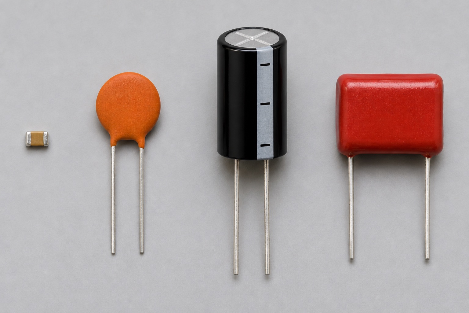
Illustrated capacitor forms: ceramic disc, radial aluminium electrolytic can, red film box and tiny multilayer ceramic chip
Appearance illustration of 4 common physical forms. Generated for teaching, not a photograph of the models below; size and markings are not exact. See the in-site model notes for verified details.

Recognise and choose

What forms will you encounter?

01Tiny beige chip, lower left

Multilayer ceramic chip (MLCC)

How to recognise it
Unmarked beige rectangle with metal ends; usually non-polarized.
Use it when
Local IC supply decoupling and compact filters close to a PCB trace or pin.
Check before choosing
Package, dielectric and effective capacitance under DC bias; nominal value alone can mislead.

Model notes on this siteMurata GRM188R71E104KA01 →

02Orange disc, left

Leaded ceramic disc

How to recognise it
Round coated disc with two radial leads; generally non-polarized.
Use it when
Through-hole filtering. For connections to mains, use only a part certified for the required X or Y safety class.
Check before choosing
Capacitance, dielectric, voltage and any required safety certification.

Model notes on this siteMurata DE1 series (X1/Y1 certified variants) →

03Black cylindrical can, centre

Radial aluminium electrolytic

How to recognise it
Cylindrical can with both leads exiting one end and a polarity stripe on the sleeve.
Use it when
Bulk supply smoothing where tens to thousands of microfarads are needed.
Check before choosing
Polarity, voltage, ripple-current rating, ESR, lifetime and temperature.

Model notes on this sitePanasonic EEU-FR1V101 →

04Red rectangular block, right

Box film capacitor

How to recognise it
Moulded rectangular case with two leads; usually non-polarized.
Use it when
Signal coupling, timing and filtering where film characteristics are useful.
Check before choosing
Film type, tolerance, voltage and frequency-related loss; ordinary DC film parts are not automatically mains safety parts.

Model notes on this siteWIMA MKS 2 →

At a glance

A capacitor stores electric charge and opposes a sudden change in voltage. Its useful value depends on voltage, frequency, temperature and construction.

This guide explains a component family. Check the exact part number and manufacturer datasheet before building.

Key specifications

Capacitance
Nominal charge per volt, in farads (F)
Voltage rating
Maximum specified voltage under stated conditions
Tolerance and dielectric
Value spread and temperature/voltage behavior
ESR and ripple current
Loss and heating limits, especially in power circuits

Circuit Lab

Put this component into a circuit

How does a capacitor charge and discharge through a resistor?

Change
Capacitance, resistance, supply voltage and initial voltage
Observe
Voltage-versus-time curve and RC time constant

Explore the linked experiments using their stated model assumptions. Device-specific limits still come from the linked datasheets.

How it works

The ideal relation is Q = C × V; current flows while voltage changes: i = C × dV/dt. A capacitor can smooth a supply, couple a changing signal or set timing with a resistor. A discharged capacitor can draw a large initial current if the source does not limit it.

Types and construction

C0G/NP0 ceramic capacitors are stable but usually available at smaller capacitance. X5R/X7R multilayer ceramics offer larger nominal values but can lose effective capacitance under DC bias. Aluminum electrolytic and tantalum or polymer capacitors are generally polarized; consult the exact series for ripple and lifetime limits.

Worked example

An ideal 10 kΩ resistor and 100 µF capacitor have a time constant τ = R × C = 1 s. After one τ of charging from an ideal 5 V step, capacitor voltage is about 3.16 V (63.2% of the final value). Leakage, tolerance and DC bias can shift real timing.

Reading a datasheet

Verify voltage rating, capacitance tolerance, dielectric, effective capacitance versus DC bias, temperature range, ESR, ripple current and polarity when relevant. For an electrolytic, also review lifetime at the specified temperature and ripple.

Common mistakes

  • Using the printed X7R/X5R value as the effective capacitance at operating voltage.
  • Reversing a polarized capacitor.
  • Assuming voltage rating alone guarantees low heating under ripple current.

Explore further

Source and review

Reviewed 18 November 2026 against Murata, ceramic capacitor DC bias FAQ. Examples are simplified educational models; ratings and pinouts depend on the exact device.