Learn how resistance, tolerance, power and temperature ratings affect a real circuit.
How it works
For an ideal DC resistor, V = I × R and P = I²R = V²/R. A series resistor limits current only when the supply, load voltage and resistor are considered together. In a divider, any connected load changes the effective lower resistance.
Types and construction
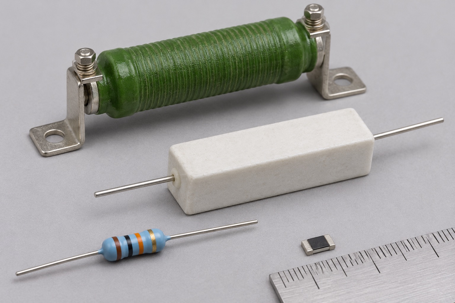
Metal film parts are common where accuracy and low noise matter; thick film chip resistors are compact and widely used; wirewound parts can handle more power but may have appreciable inductance. Construction alone does not establish a rating: compare actual series data.
Worked example
A 1 kΩ resistor across 5 V carries 5 mA and dissipates 25 mW. A 10 kΩ + 10 kΩ divider on 5 V gives 2.5 V unloaded; adding a 10 kΩ load across the lower resistor reduces the output to about 1.67 V.
Reading a datasheet
Check resistance range, tolerance, rated power and its derating curve, maximum working voltage, temperature range and any pulse rating. Surface mount power ratings depend on PCB copper and test conditions.
Common mistakes
- Treating the nominal resistance as an exact measured value.
- Ignoring power derating or applying a wattage rating under different mounting conditions.
- Using an unloaded divider equation after attaching a significant load.
Explore further
Source and review
Reviewed 18 November 2026 against Vishay, Basics of Linear Fixed Resistors. Examples are simplified educational models; ratings and pinouts depend on the exact device.