Components / LEDs

LEDs: Polarity, Forward Voltage and Current

Select a current limit and check LED polarity, forward voltage and thermal limits.

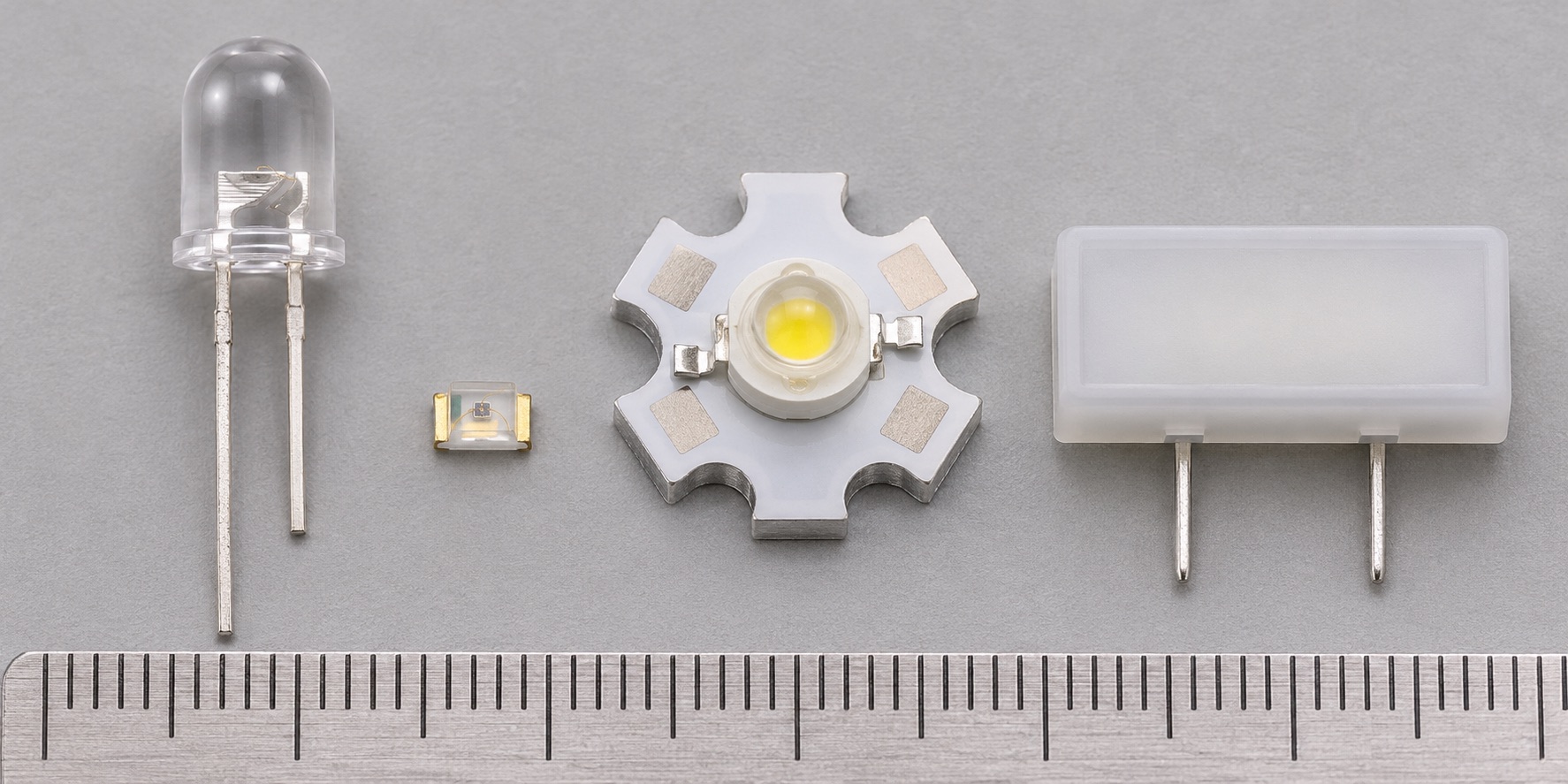
Illustrated LED forms: clear through-hole lamp, tiny surface-mount LED, high-power LED on a star board and rectangular board indicator
Appearance illustration of 4 common physical forms. Generated for teaching, not a photograph of the models below; size and markings are not exact. See the in-site model notes for verified details.

Recognise and choose

What forms will you encounter?

01Clear round lamp, left

Through-hole indicator LED

How to recognise it
Round epoxy lens with two leads; lead length and body flat may help, but use the datasheet for polarity.
Use it when
Breadboards, panel indicators and hand-assembled boards.
Check before choosing
Forward current and voltage, viewing angle, brightness and polarity.

Model notes on this siteKingbright WP7113ID →

02Tiny chip, centre-left

Surface-mount indicator LED

How to recognise it
Small flat rectangular LED with package-specific polarity mark.
Use it when
Compact PCB status lights, often behind a light pipe or diffuser.
Check before choosing
Footprint, polarity, Vf, brightness at the planned current and soldering limits.

Model notes on this siteKingbright APHHS1005LSECK/J3-PF →Cree LED CLM2D series →

03Emitter on star-shaped board, centre

High-power LED emitter

How to recognise it
A bright emitter on a thermal pad, often mounted on a metal-core carrier board.
Use it when
Illumination when a constant-current driver and suitable heat path are provided.
Check before choosing
Drive current, thermal resistance, junction temperature and optical bin.

Model notes on this siteCree LED XLamp XP-G3 series →

04Rectangular housing, right

Circuit-board indicator assembly

How to recognise it
LED lens built into a plastic housing that positions the light at an enclosure opening.
Use it when
Front-panel status indication when LED height and alignment must be repeatable.
Check before choosing
Mechanical dimensions, polarity, colour and whether the assembly contains a resistor.

Model notes on this siteKingbright WP934 series →

At a glance

AnodeCathode

A light-emitting diode produces light when forward current flows. Its current rises steeply with voltage, so a voltage source alone does not set a safe operating current.

This guide explains a component family. Check the exact part number and manufacturer datasheet before building.

Key specifications

Forward voltage (Vf)
Voltage at a specified current and temperature
Forward current (If)
Recommended operating and maximum values
Polarity
Anode and cathode identified by the exact package drawing
Optical and thermal data
Brightness, wavelength, viewing angle and heat limits

Circuit Lab

Put this component into a circuit

How does a resistor set LED current and brightness-related operating point?

Change
Supply voltage, LED Vf range, target current and resistor
Observe
Estimated current and resistor/LED power
Try a related tool →

Explore the linked experiments using their stated model assumptions. Device-specific limits still come from the linked datasheets.

How it works

A small indicator LED is commonly driven through a series resistor. Estimate R = (Vs − Vf) / I, then check the chosen standard value and worst-case tolerances. High-power LEDs generally need a suitable constant-current driver and thermal path.

Types and construction

Through-hole indicators, surface mount indicators and power LEDs differ greatly in optical output, electrical ratings and heat removal. Color alone does not uniquely determine Vf; the actual part and test current matter.

Worked example

Assuming a 5 V supply, one LED at Vf = 2 V and a 330 Ω resistor, the fixed-Vf model gives I ≈ 9.09 mA. Resistor dissipation is about 27 mW. This is a worked estimate; recalculate for the actual LED’s Vf range and supply tolerance.

Reading a datasheet

Check the exact package pinout, forward current, Vf at specified test current, reverse-voltage limit, optical data, ambient-temperature derating and junction-temperature or mounting requirements.

Common mistakes

  • Connecting an LED straight across a voltage source without current control.
  • Assuming all colors and packages have the same Vf.
  • Using the typical Vf as a guaranteed worst-case value.

Explore further

Source and review

Reviewed 18 November 2026 against Cree LED, CLM2D red/amber SMD LED datasheet. Examples are simplified educational models; ratings and pinouts depend on the exact device.