Components / Potentiometers

Potentiometers: Dividers and Variable Resistance

Understand the wiper, taper, total resistance and power limits.

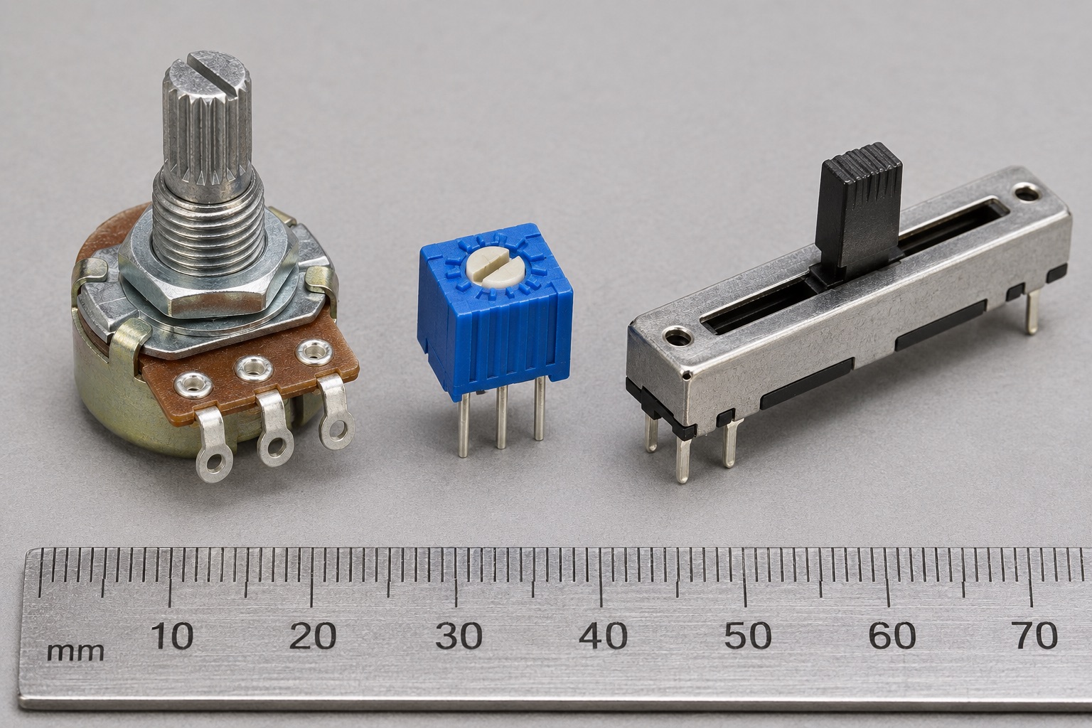
Illustrated potentiometer forms: panel rotary knob control, small blue board trimmer and long slide potentiometer
Appearance illustration of 3 common physical forms. Generated for teaching, not a photograph of the models below; size and markings are not exact. See the in-site model notes for verified details.

Recognise and choose

What forms will you encounter?

01Round body with shaft, left

Panel rotary potentiometer

How to recognise it
Three terminals and a shaft for a user-facing knob.
Use it when
Repeated manual adjustment such as level or setpoint control.
Check before choosing
Resistance, linear or audio taper, shaft size, rotational life and wiper loading.

Model notes on this siteBourns PDB181-GTR →

02Small blue screw-adjusted part, centre

PCB trimmer potentiometer

How to recognise it
Compact body with a screwdriver adjustment and three electrical terminals.
Use it when
Occasional calibration inside equipment, not daily user control.
Check before choosing
Turns, adjustment direction, total resistance, wiper current and sealing.

Model notes on this siteBourns 3296 →

03Long track with slider, right

Slide potentiometer

How to recognise it
Linear slot and movable finger tab; electrical action is still a three-terminal wiper.
Use it when
Faders where the control position should be visible at a glance.
Check before choosing
Travel, taper, mounting, mechanical life and wiper load.

Model notes on this siteBourns PTA series →

At a glance

A potentiometer is a resistor element with a movable wiper. Three terminals make an adjustable divider; two terminals make a variable resistance.

This guide explains a component family. Check the exact part number and manufacturer datasheet before building.

Key specifications

Total resistance
Resistance end-to-end
Taper
Wiper-position relationship, often linear or audio/log
Power rating
Element dissipation under specified conditions
Wiper current
Maximum permitted current through the moving contact

Circuit Lab

Put this component into a circuit

Why does loading the wiper change the expected divider voltage?

Change
Total resistance, wiper position, taper and load resistance
Observe
Unloaded versus loaded output and track power
Try a related tool →

This describes a learning model for a future experiment. Device-specific limits still come from the linked datasheets.

How it works

With a high-impedance output load, the wiper of a linear potentiometer produces a fraction of the end-to-end voltage. Loading the wiper changes that fraction. As a two-terminal rheostat, the wiper contact carries load current and may need a different rating check.

Types and construction

Panel controls, trimmers and digital potentiometers serve different adjustment needs. Mechanical devices vary in taper, rotational life, sealing and power. A digital potentiometer has additional supply and terminal-voltage limits.

Worked example

A 10 kΩ linear potentiometer across an ideal 5 V supply draws 0.5 mA and dissipates 2.5 mW end-to-end. At its midpoint the unloaded wiper is approximately 2.5 V; a low-resistance load will pull that voltage away from 2.5 V.

Reading a datasheet

Read total resistance tolerance, taper, power derating, maximum wiper current, end resistance, mechanical life and terminal labeling. A full-element power rating does not automatically permit the same current through every short wiper segment.

Common mistakes

  • Assuming midpoint voltage stays exact after attaching a load.
  • Using an audio taper as if position-to-voltage were linear.
  • Ignoring the wiper-current or partial-track power limit.

Explore further

Source and review

Reviewed 18 November 2026 against Bourns, Potentiometer Handbook. Examples are simplified educational models; ratings and pinouts depend on the exact device.